Products Info
PRODUCT
Synchro-type Position Transmitter FM2 Series
Overview
The synchro-type position transmitter is mounted on the final control element and generates an AC voltage proportional to its position. This voltage is rectified and converted into a DC signal,
which is used as the feedback signal for an electro-hydraulic controller or to indicate the position of the final control element in the control room.
Features
The conductive sliding section uses a surface-contact method and the rotor winding is molded, providing good durability and particularly high resistance to vibration.
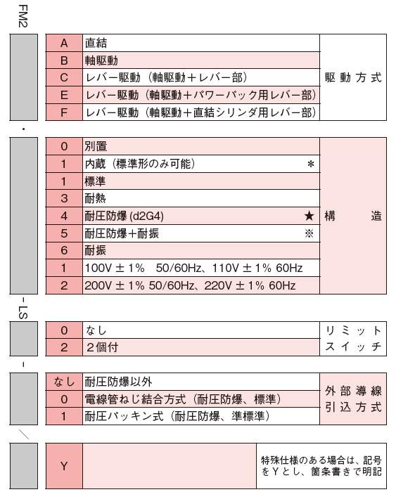
Three mounting types are available (direct-coupled, shaft-driven and lever-driven), allowing installation on many types of final control elements.
Limit switches can be installed.
Operating Principle
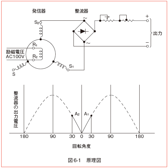
A synchro is used as the element that converts the input rotation angle into an electrical signal.
The structure of the synchro is similar to that of a small three-phase AC machine, with a single-phase primary winding on the rotor and three-phase secondary windings on the stator.
When the primary winding is connected to an AC power supply, a sinusoidal voltage corresponding to the angle of each secondary winding relative to the primary winding is induced in each secondary phase. This voltage is full-wave rectified by a rectifier circuit and converted into a DC signal.
To increase the output voltage when the control shaft rotates in a given direction, use the range 0–A1 (30°); to decrease it, use the range A2–0 (30°).
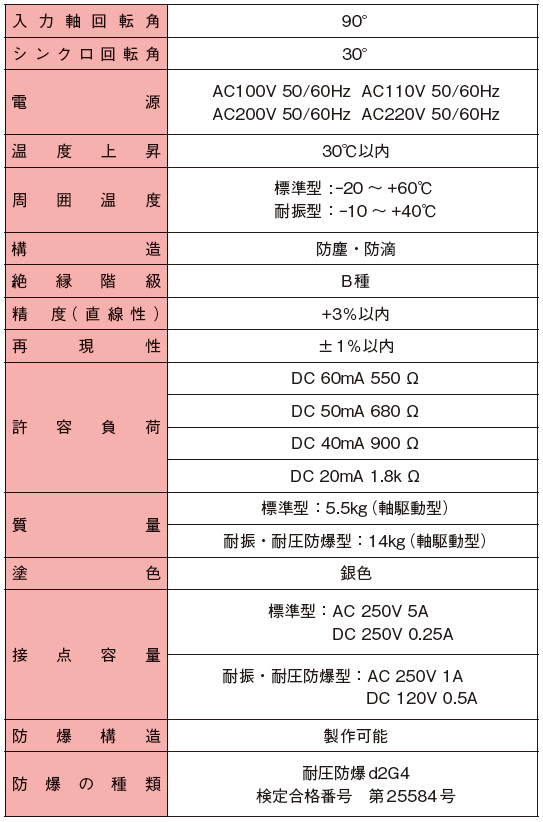
For 4–20 mA DC, however, use the range 7.5–37.5°.
Specifications